A simpler way to reach important phone actions
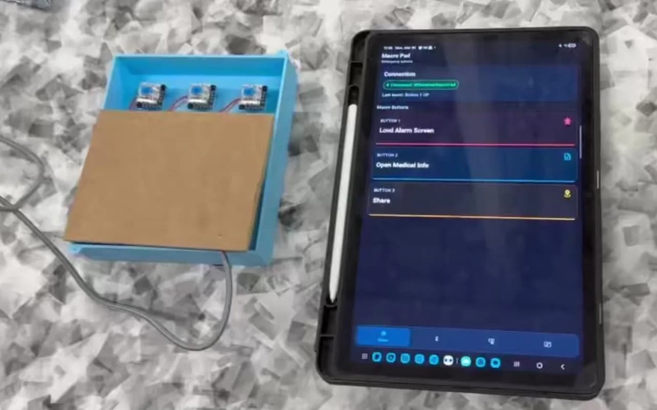
Our engineering design class asked each team to build around a client interview. Mark explained that limited dexterity made precise touchscreen interactions difficult. Our five-person team responded with a separate controller: three large buttons connected to a configurable Android app.
The final prototype could sound an alarm, call a trusted contact, share location, send an SOS message, open medical information, or place an emergency call. It was a working proof of concept rather than a finished assistive product.
What I worked on
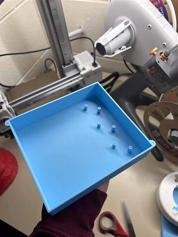
I coordinated meetings and divided tasks, but my main technical responsibility was the complete physical prototype. I designed the enclosure and keycaps, developed and built the circuit, soldered the connections, and handled hardware integration and debugging.
I also contributed to the ESP32 firmware, React Native app, and testing the full path from a button press to its assigned mobile action.
The first direction
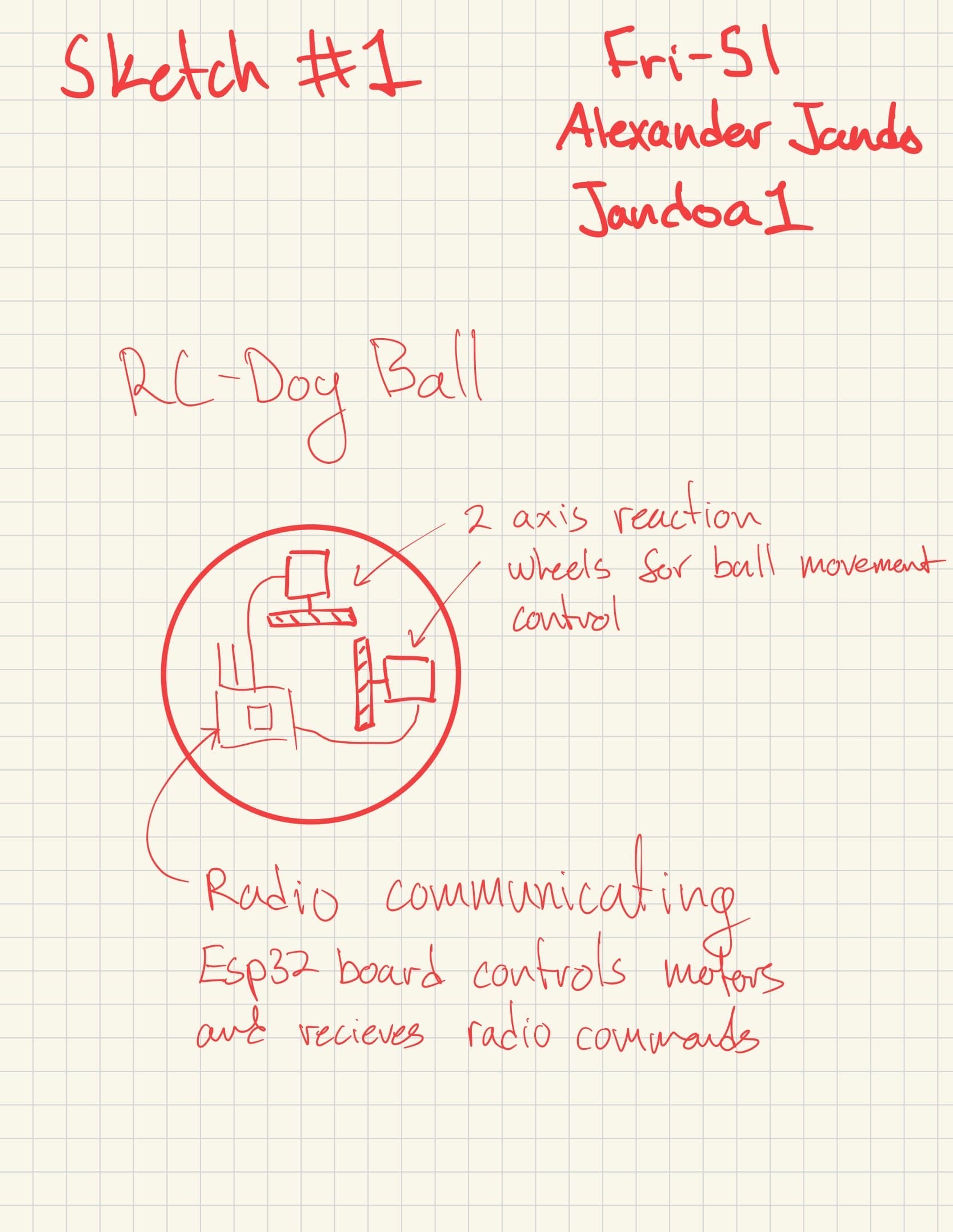
We initially explored a reaction-wheel ball that could help Mark play with his dog, Rosie. Sketching the mechanism made the idea easier to evaluate, but it also exposed the amount of mechanical and control risk involved.
We returned to Mark’s interview and compared what would be useful with what we could build and test well. That led us to the macro pad, a different challenge that combined accessible hardware, embedded firmware, Bluetooth, and a mobile app.
Designing the physical controller
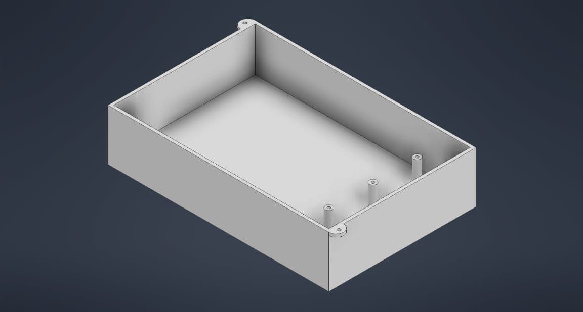
The controller used three widely spaced mechanical switches with custom 30 mm keycaps. Their tactile bump and audible click made activation easy to confirm. I designed the enclosure around the switches, ESP32, circuit, cable access, and mounting points.
Cherry MX Blue switches are not ideal for every user because they still require noticeable actuation force. A future version should compare softer switches through user testing instead of assuming one switch works for everyone.
From a key press to a phone action
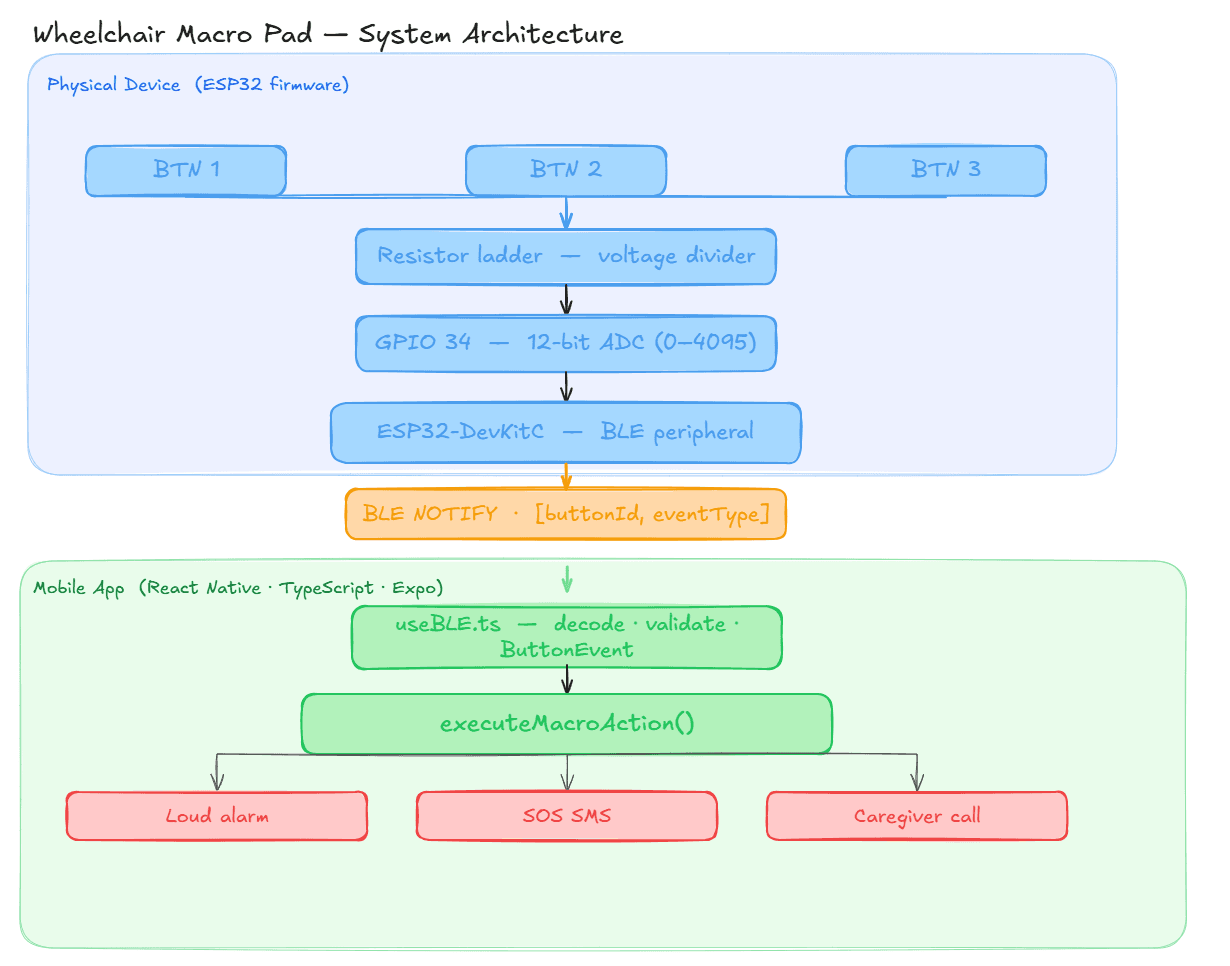
- ReadThe ESP32 averages ADC samples and identifies the pressed key from its voltage range.
- FilterCalibrated dead zones and a 150 ms debounce window reject noisy readings.
- SendThe ESP32 reports press and release events over Bluetooth Low Energy.
- RunThe app decodes the event and launches the action assigned to that key.
Three switches through one input
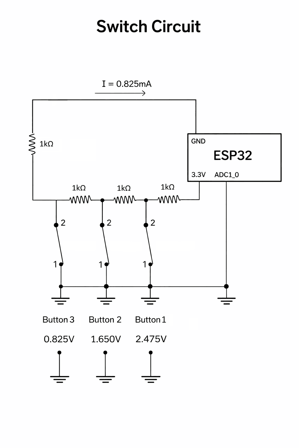
A resistor ladder produced a different voltage for each switch, about 0.825 V, 1.650 V, and 2.475 V. This let the ESP32 distinguish all three buttons using a single ADC pin.
Serial readings helped us calibrate the ranges around each voltage. We later widened those ranges and averaged multiple samples to make detection more reliable.
The first build did not hold up
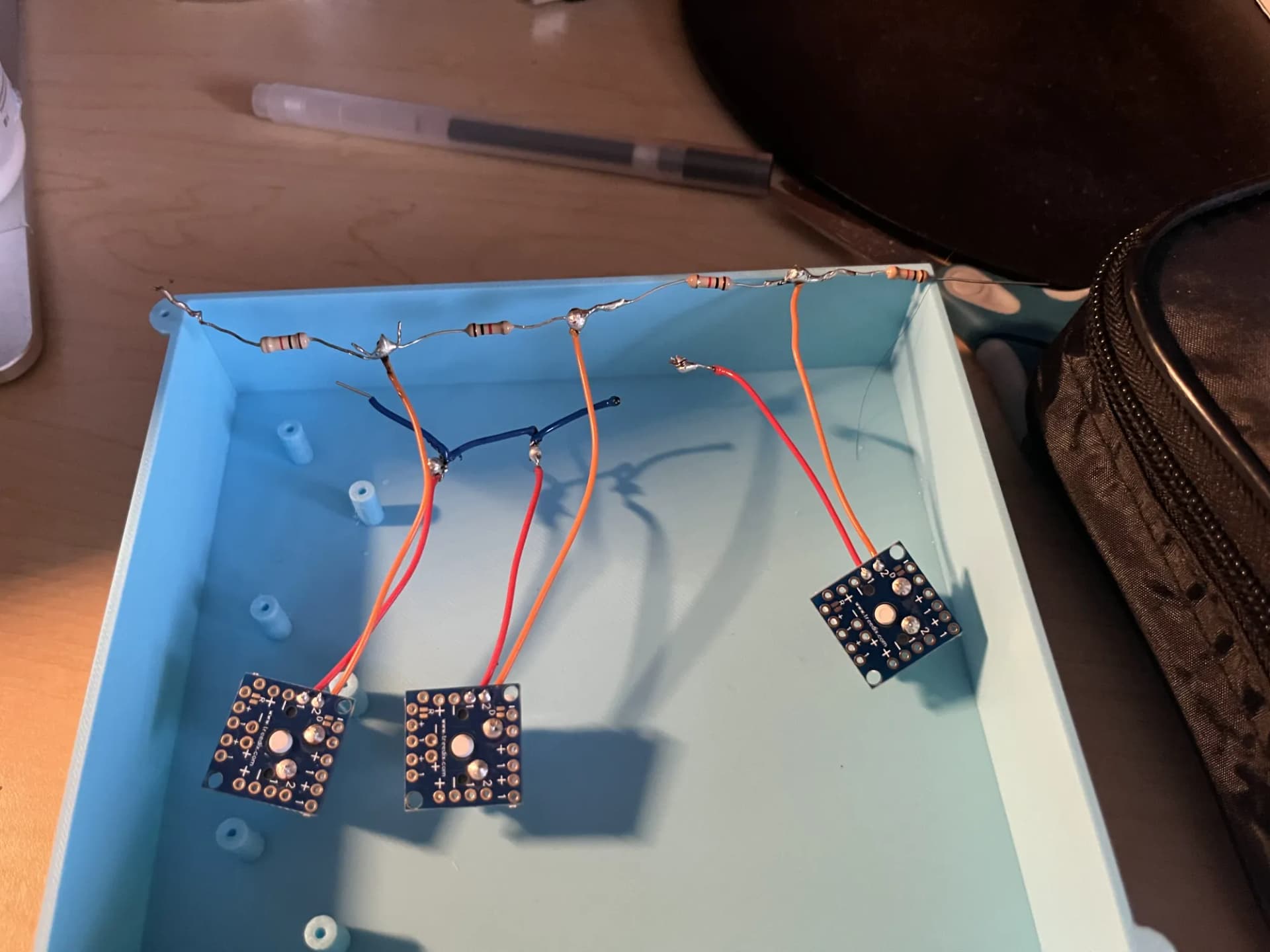
My first free-form circuit looked compact, but several solder joints failed and the tightly packed connections made faults difficult to isolate. I had to practise my soldering, rebuild the connections, and change how I approached the prototype.
Rebuilding for easier testing
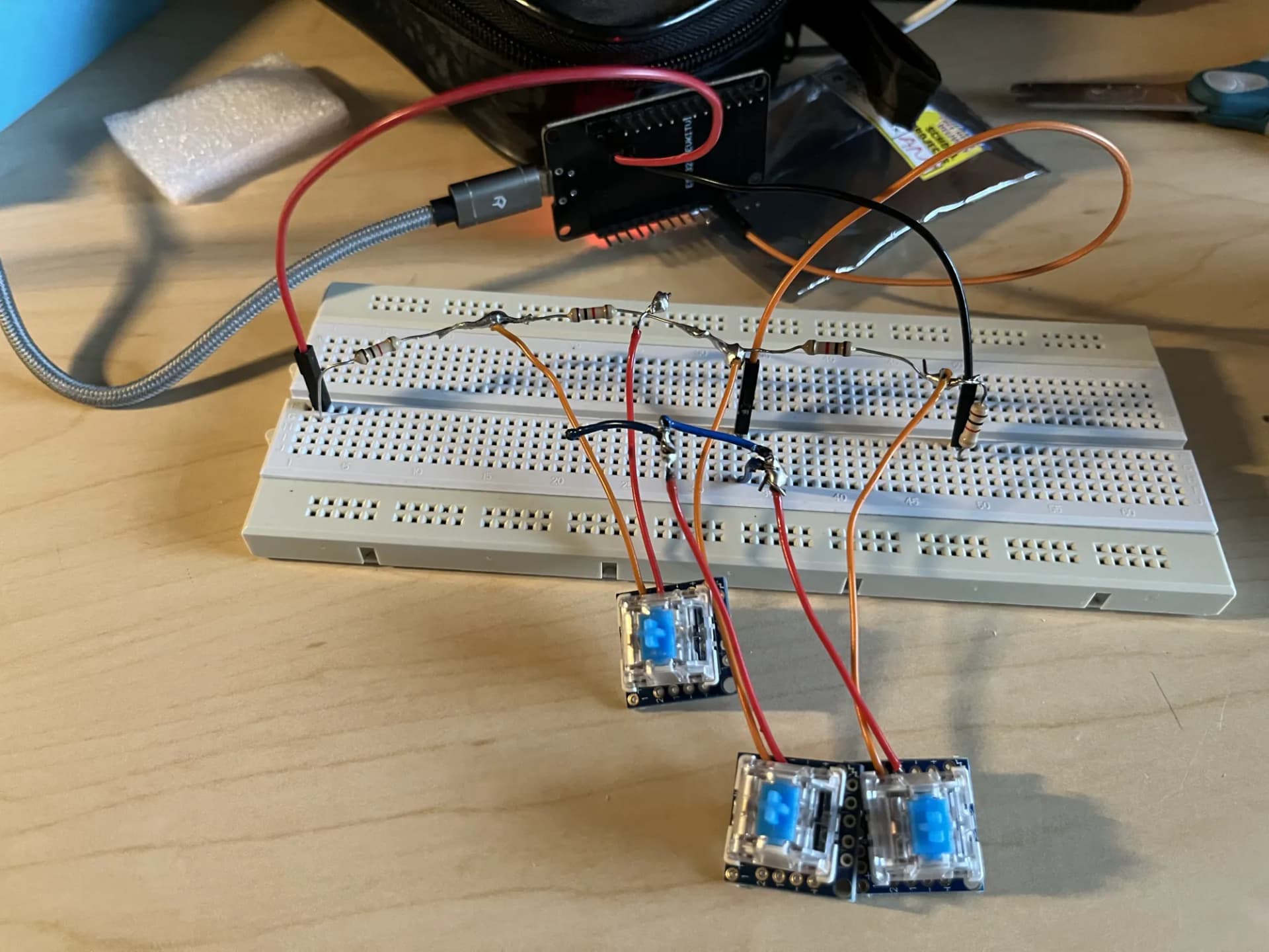
Moving the circuit to a breadboard made every connection easier to inspect, probe, and change. Serial ADC readings exposed noise near the original thresholds, so we added sample averaging, wider voltage ranges, and longer debouncing.
The revised layout took up more space, but it made debugging much faster. By the final demonstration, every button consistently produced the correct event.
The final demonstration
All three inputs were recognized correctly, BLE events reached the Android app, all six configured actions worked, and button assignments persisted after the app was closed and reopened.
We demonstrated the system on a Samsung Galaxy Tab S10 FE. We did not run a long-term usability trial with Mark, so the result should be understood as a complete proof of concept rather than a validated assistive product.
My biggest hardware lesson was simple: compact is not the same as reliable. A circuit that is easy to inspect and change is often the faster path to a working design.
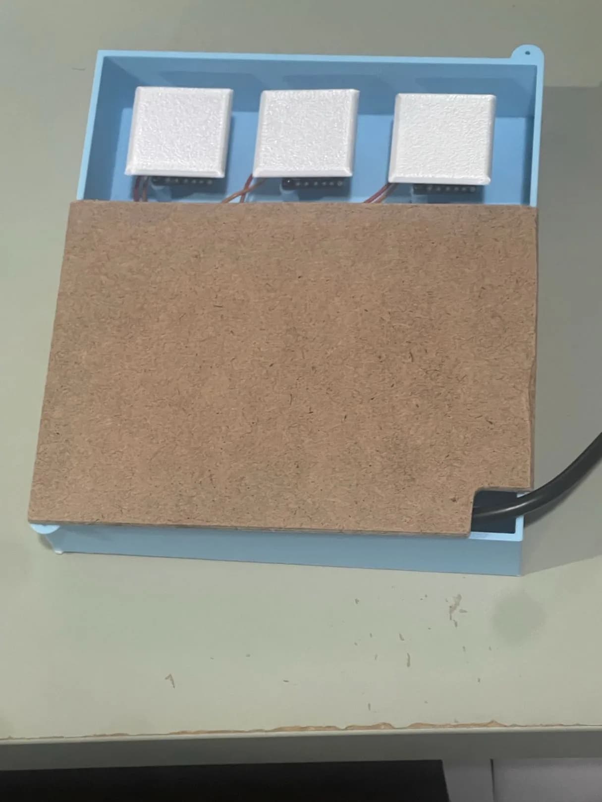
A next version should replace the breadboard with a custom PCB, improve internal wire management, use a tougher enclosure, run from a battery, and test softer switches and mounting options with users over time.